Week 4: Electronics Production
Assignment:
- Make an in-circuit programmer by milling the PCB
- Optionally, trying other processes.
- For this week we have to make the FabISP board.
The FabISP is an in-system programmer for AVR microcontrollers, designed for production within a FabLab. It will allows us to program the microcontrollers on other boards we make.
The Electronics Production assignment is to construct the board, stuff it with components and program it, when we create another boards during the Fab Academy, we'll use this board to program them.
Machines:
- Trotec Speedy 100
- Milling CNC
- Soldering Heat Gun
Software:
Materials:
- Spray Paint
- Solvent
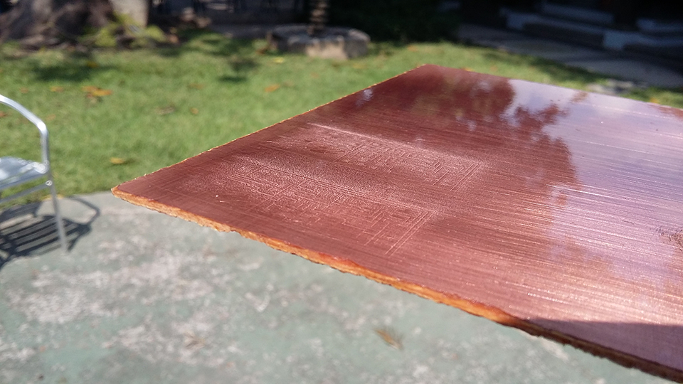
- Copper Board
- Ferric Perchloride
- 1/32" Drill
- Solder Paste
- Tweezers
- Antistatic table
Electronic Components:
- 1 ATTiny 44 microcontroller
- 1 Capacitor 1uF
- 2 Capacitor 10 pF
- 2 Resistor 100 ohm
- 1 Resistor 499 ohm
- 1 Resistor 1K ohm
- 1 Resistor 10K
- one 6 pin header
- 1 USB connector
- 2 jumpers - 0 ohm resistors
- 1 Crystal 20MHz
- 2 Zener Diode 3.3 V
- 1 usb mini cable
- 1 ribbon cable
- two 6 pin connectors
CLASIFICATION OF ELECTRONIC COMPONENTS
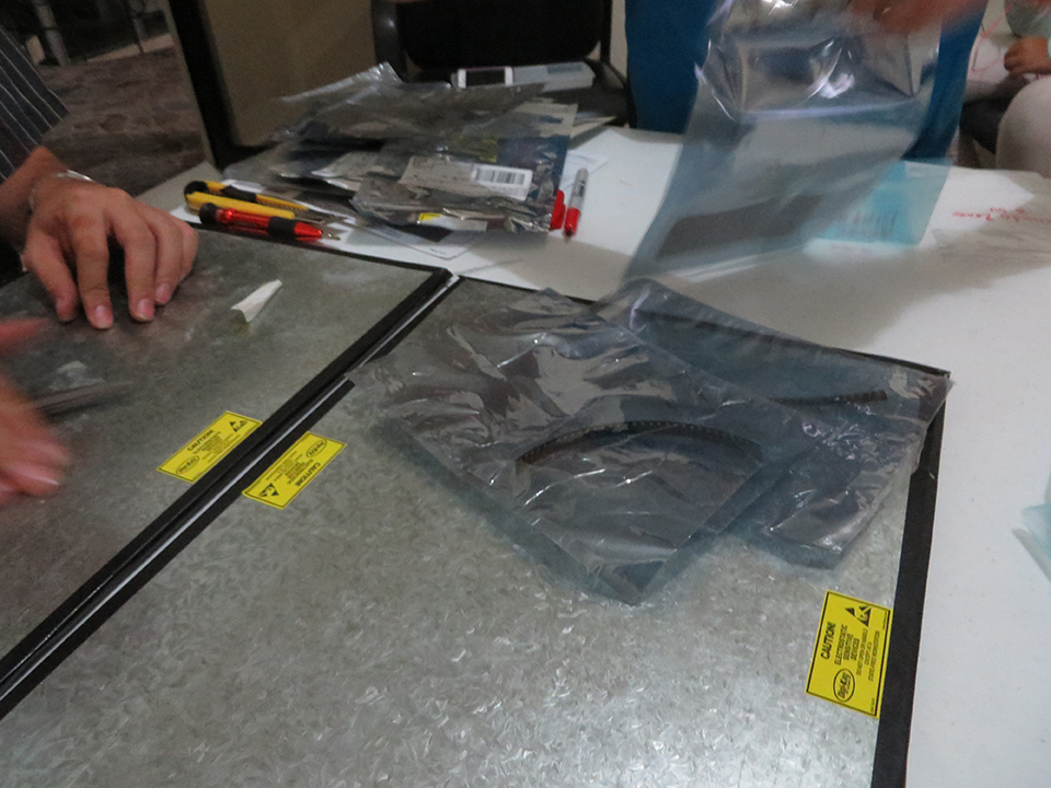
We received all the components that we are going to use in the Fab Academy’s electronic assignments. We needed to classify and package them separately, and some other that must been package in special conditions, because they are humidity sensitive and letting them expose could mean their deterioration.
CREATE A PCB IN A LASER CO2
As we have no access to a milling machine in the lab, we had to fabricate our PCB’s with a different process, so we decided to try with laser engraving as a suggestion of one of the Hackerspace San Salvador staff member.
First of all, we based in this tutorial: http://www.instructables.com/id/Custom-PCB-Prototyping-using-a-Laser-Cutter/
At the beginning we didn’t have all the necessary items, so first we tried with Transparent Acrylic Coating Spray, later we realized that didn’t matter the changes of speed and power we set, there was always a thin coating layer that, we knew, will never let us etching the PCB; so, we had to change the coating spray.
What failed? Well we have a couple of theories:
- The surface of the acrylic coating and/or the surface of the copper reflects part of the energy to the environment, and impeded the laser vaporize the whole coating.
- The transparency of the acrylic caused the refraction of the laser dissipating its energy.
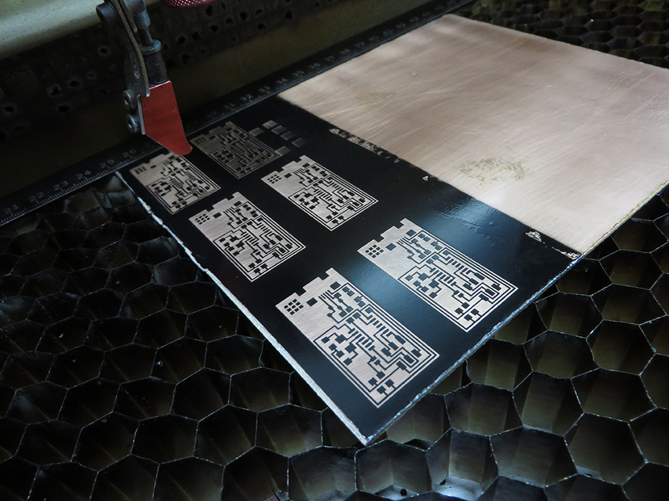
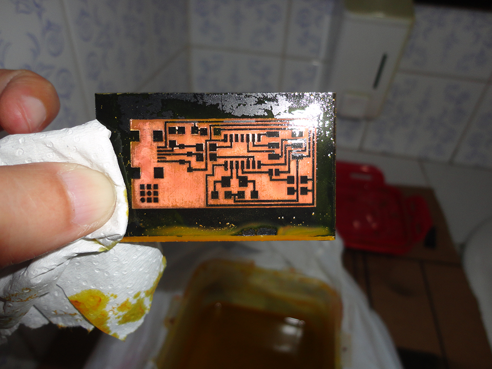
Second try, this time we used a Glossy Black Painting Spray, in this attempt it was easier to see the effect of the laser on the painting, but just like before, in a different way, it looked a thin layer of black paint, this time, more dispersed; so we tried different speeds and power to improve the results. It looked promising and we decided to try the etching process. We prepare the ferric perchloride and submerged one of the recently engrave PCB and voilà, it was HY-DRO-PHO-BIC! This means that repels the water.
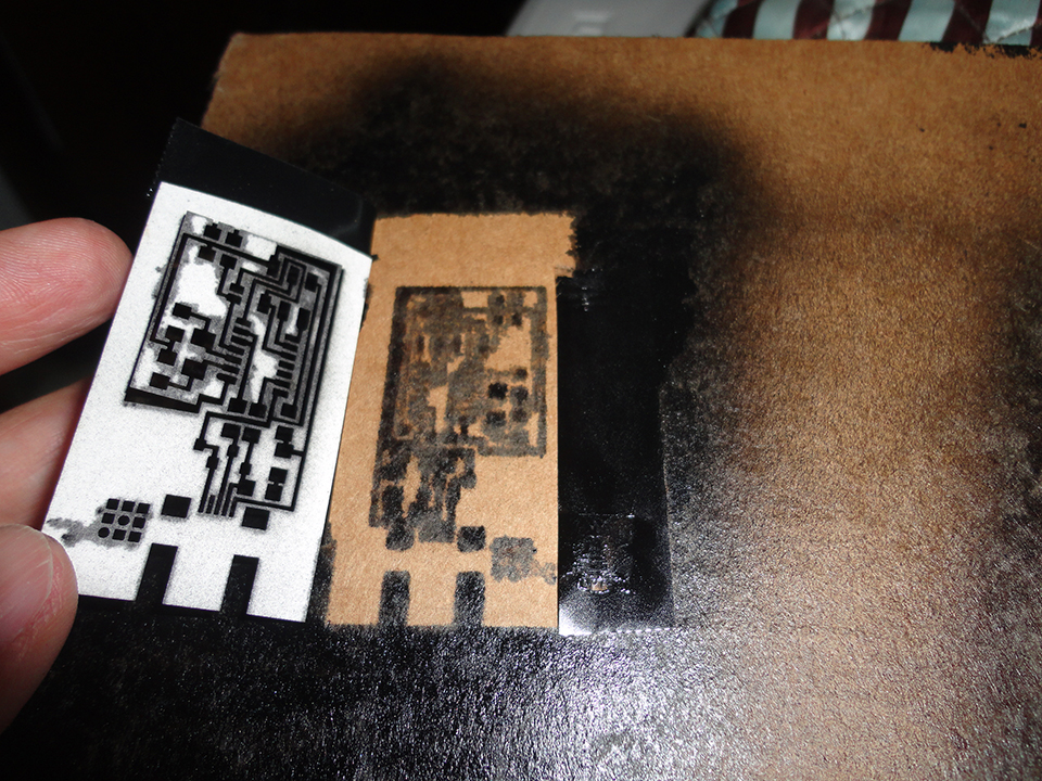
But, why did it fail again? In this case we formulate the hypothesis that the laser reach some point too close to the copper, and this caused that the energy dissipates. Maybe the energy it is only enough to degrade the colorant of the paint, but the binder remains, and again, a thin coating layer doesn't let the ferric perchloride etch the PCB.
Third try, we cut a stencil that would help us to cover the parts of the board that we didn't want to paint, but the tracks were very thin and when we applied the spray, the paint always reach under them and mess the whole circuit board.
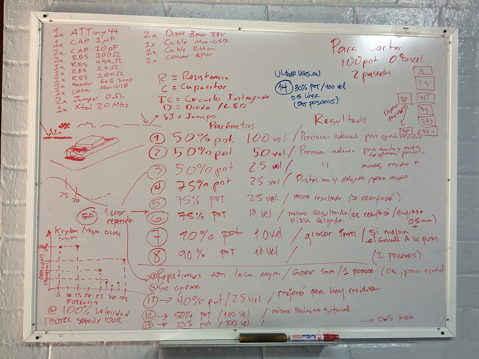
Recapitulating, during the experiment we had to change some parameters such as:
- Paint
- Speed
- Power
- Thickness of image circuit tracks
We took notes during all the iterations and these are the results and our observations:
CLEANING AND ETCHING
So we decided to continue and try cleaning the second try’s board, the parts where it’s supposed there is only copper, with isopropyl alcohol, but we had to be very, very, very careful; because otherwise we could erase parts of the circuit, since isopropyl alcohol is used as a solvent and have the capacity to clean all the paint. We also tried with a commercial remover, but it worked almost the same.
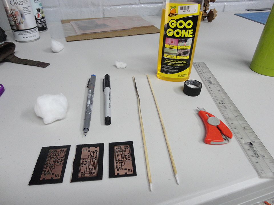
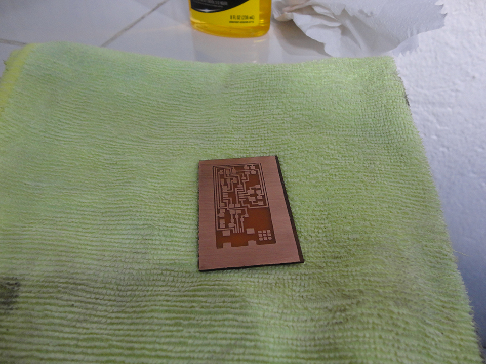
We have to be honest, when we were cleaning we messed up like 8 PCB to get 3 that we can use to continue with the soldering process. So we prepared the ferric perchloride and etched the surviving PCBs.
We’ll try with Flat Black Painting Spray too, just to check if the matte spray leaves the same thin coating layer on the board or not, may be is easier to clean and makes the etching process faster.
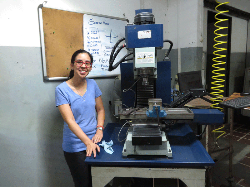
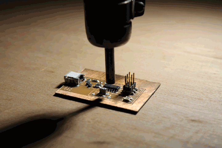
MILLING CNC PROCESS
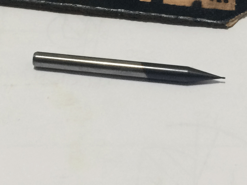
I also tried to mill the Fab ISP in a Chinesse Milling Machine using a 1/32" drill tool because the board details.
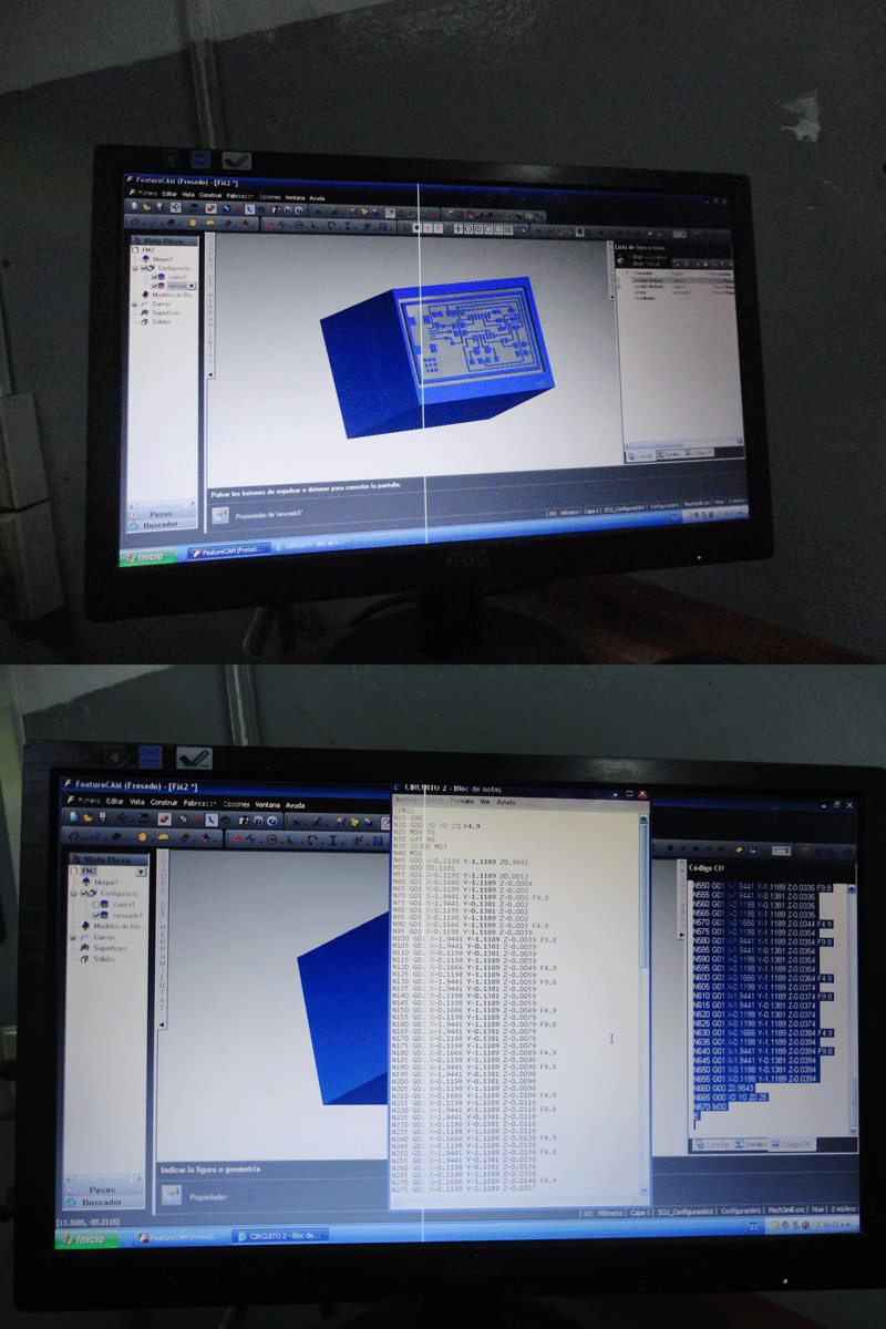
I already have the Fab ISP vector file because I used it with the laser CO2 machine too, so the first step was save the vector file as DWG format to be able to import it in Feature CAM, the software that converts the file into GCode the milling machine understands. Here I set the tool I used, the material kind and thikness.
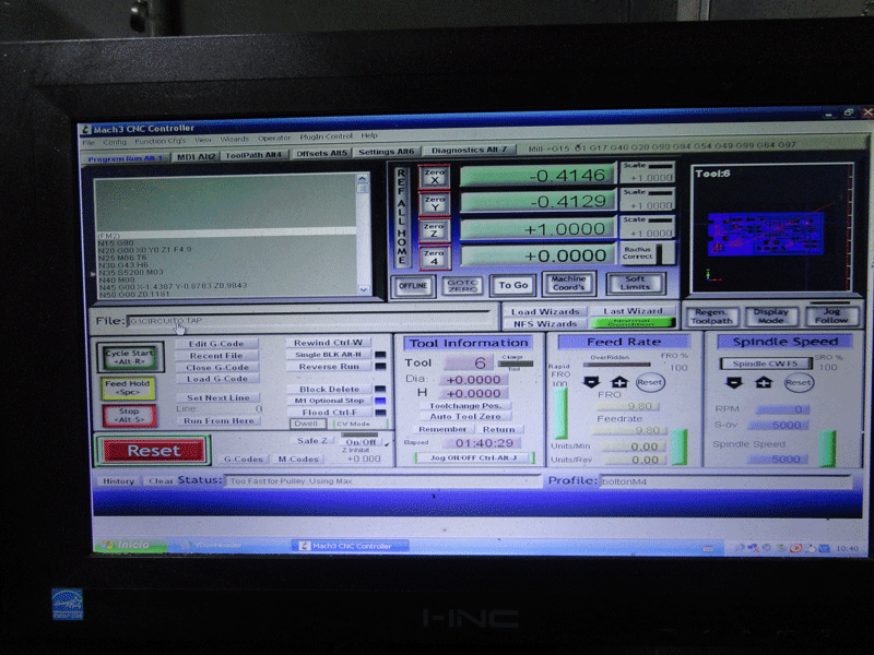
Once the GCode was generated, I opened it in Mac3 CNC Controller, that is the milling CNC controller, pushing the "Cycle Start" button the milling starts to work, but first I had to fix the copper board and calibrate the X, Y and Z axes.
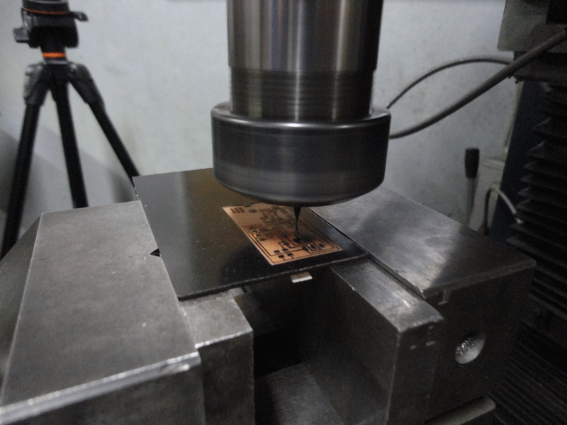
Here are the results, the copper is covered with black paint because I didn't have another clean piece, just the one I used engraving in the laser CO2 machine.
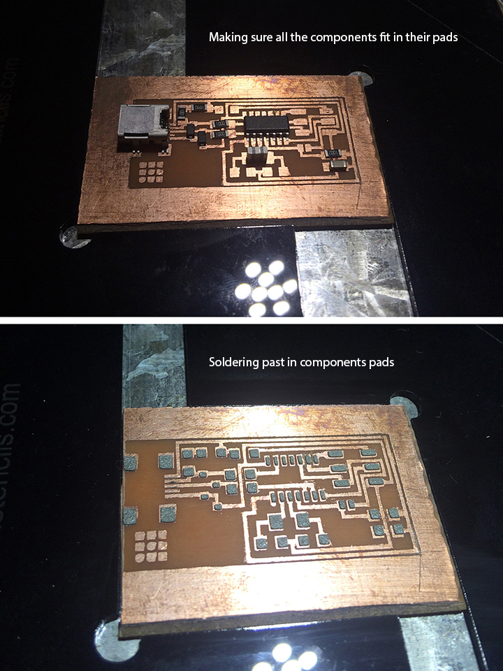
SOLDERING PROCESS
To solder the board first we fixed them to the table, then we use a stencil to apply a thin paste; the stencil only have to have the spots where the pins of the elements are going to be solded, and we have to apply it with a plastic card making sure to cover all the holes, we could repeat this process the times we needed, inclusive change the stencil if necessary because we punch the holes in cardstock with the same laser cutter we use for engraving.
When we finish to apply the soldering paste, we have to place all the components carefuly, as almost all the necessary components are tiny, this was the part that toke more time, we had to be carefuly with the diodes becouse they have polarity, and with ATTiny 44 because is sensible to electrostatic. To manipulate components we used a pair of anti-static tweezers.
After we finished to plac all the components, we used a heat gun the welding them, this machine blows hot air and makes the soldering paste melt fixing the components to the board and allows the electrical conduction among them.
And finally we have to check all the connections, and if everything is alright, it is only needed to clean the board with contact cleaner and it’s ready to be programed.
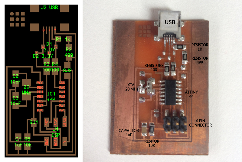
This is the FabISP finished, I had to remove the Zener Diodes 3.3 V because they made my FabISP work wrong.
My electronics instructor explained to me that the Zener diodes function is a protective measure, in an application that is commonly known as clamp or trimmer in order to protect against electrostatic discharges. USB is a high-speed protocol very susceptible to capacitance, which is the measure of its capacity to store charge, and what happened was that the diodes weakened the signal and the computer and the microcontroller didn't understand each other. As the component is not critical, removing them desn't affect the Fab ISP performance, so I removed them and now it works very well.
Now it's working well and I could programm it.
PROGRAMING THE FabISP
To program my FabISP I had to install avrdude and GCC, to do that I downloaded Crosspack AVR and XCode for Mac OS, and FabISP Firmware.
Once everything installed in my computer, I connected the FabISP to an USB port and I used an Arduino UNO to program the board.
I followed the next steps:
1. Open makefile in TextEdit and find the rows:
      #AVRDUDE = avrdude -c usbtiny -p $(DEVICE) # edit this line for your programmer
       AVRDUDE = avrdude -c avrisp2 -P usb -p $(DEVICE) # edit this line for your programmer
By adding a # in the begining of the second row I comment it out.
2. In terminal I navegated where I saved the downloaded firmware and write the command
make clean
3. A rutine run and then I type
make hex
4. A rutine run and then
make program
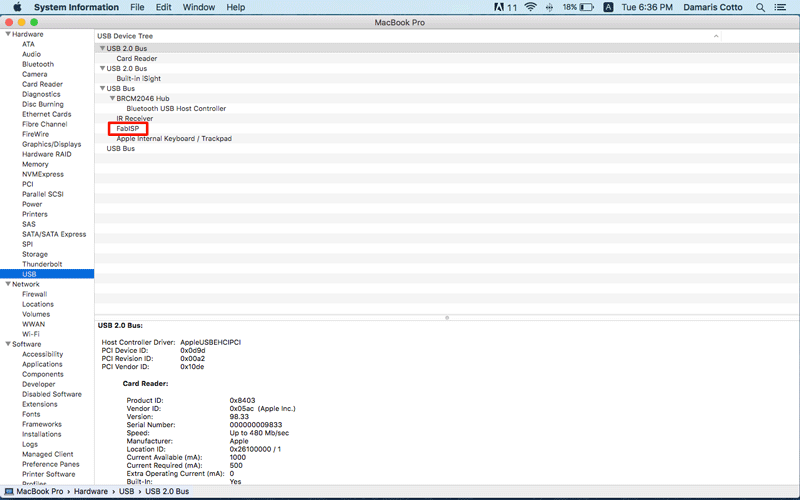
5. The FabISP is now programmed.
6. To check if it works well and the computer recognized it, I open System Report under Apple menu - About this Mac. In the Hardware - USB segment, FabISP should appear.
This assigment was sponsored by: